|
[?]Subscribe To This Site
|
Concrete Footing Design ProcessConcrete footing design, footing design, footing detail, and continuous footing all follow the same design procedure. A concrete footing detail is the end result of footing design process following careful considerations of the type of soil, climate conditions, ground water, type of structure, usage of the structure, etc.
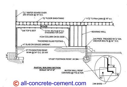
Footing design is something your normal concrete contractor or general contractor does not care much about, it is not required of them. Usually a contractor shows up in the picture after the footing design, concrete footing detail, and continuous footing are complete.Even in design-built projects, where contractors are heavily involved during design phase, they will never inquire of how footings are designed. This section is dedicated to the footing design process. For illustrative purposes, let’s consider the Building section shown here. On the left side just below the TJI floor joist shows a steel beam W12x26 across the living room. The reason for this beam was to minimize the clear span of the 11-7/8" TJI joist. Due to cost and availability of material, it was the least expensive choice to use steel beam. This beam was carried by a 4 stud column at each end which in turn transfers the load to the footings. Here are the steps and thought process that went into footing design:

Step 1: Determine the dead load Concrete footing design requires estimating the dead load, the load of building material, in this case all the material for the floor. 1. 1/2" drywall ceiling - 3.3 psf(pounds per square foot) 2. 5/8" Plywood floor sheathing - 2 psf 3. TJI Floor Joist @ 16" o.c. - 1.9 psf 4. Carpet & pad - 1 psf 5. Steel beam - 26 plf(pounds per lineal foot) Adding items 1 thru 4 yields 8.2 psf plus weight of beam Step 2: Determine the area tributary to the beam 
An important step in concrete footing design, or any footing design is determining the beam tributary area. Tributary area refers to the area of the floor carried by the steel beam, shown shaded in the plan. This means fifty percent of the area to the right and left of the beam are carried by the steel beam. Half of 7'-6" is 3'-9" and half of 17'-8" is 8'-10". Adding the two halves yields 12'-7" which is the tributary width. Multiply the tributary width by the 8.2 psf yields 103.2 plf. Adding this to the weight of the beam we have a dead load of 129.2 plf. Step 3: Determine live load (LL) The live load is given by the code as 40 psf. Multiply the LL by 12'-7", we have a 503.2 plf (40x12.58=503.2) live load carried by the beam. Per plan the beam clear span is 19 feet. Combining the dead and live loads and multiply by the beam clear span yields total load of 12,015.6 pounds [(503.2+129.2)x19=12,015.6]. Since there are two columns, one will carry 50% of the load. Each column carries 6,008 pounds(round off to nearest whole number). Step 4: Determine soil pressure and calculate area of footing Since no soil testing was done for this project, the rule of thumb is to use 1,500 psf allowable soil pressure. Taking the 6,008 pounds divide by 1,500 pounds per square foot - the pounds cancel each other, leaving the end result as 4 square feet of footing area required.Since these are continuous footing the width can be used to calculate the required length. For the 1'-4" thicken slab, it requires 3 ft (4/1.33) long which is less than the footing provided. The exterior side of the footing, the width is 1'-8" which requires 2'-4"(4/1.67) footing length to satisfy the required footing area. Therefore, the footing provided is sufficient. Back to Concrete Footing Design More on footing detail concrete footing detail For continuous footings design click here |
|


