|
[?]Subscribe To This Site
|
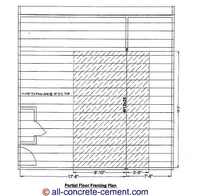
Continuous Footing DesignConcrete footing design for wall footing or continuous footing is exactly the same as designing spot footings as in concrete footing design Discover how the pros estimate the weights necessary to design continuous footings. This estimate is based on the floor shown below.Floor dead load estimate: 1. ½” drywall ceiling – 3.3 psf 2. 5/8” plywood floor sheathing – 2 psf 3. TJI floor joists @ 16” o.c. – 1.9 psf 4. Carpet & pad - 3 psf Total = 8.2 psf Total floor DL = 8.2x3.75 = 30.75 plf 
Roof Dead Load Estimate: 1. ½” drywall ceiling – 3.3 psf 2. 7/16” waferboard – 1.5 psf 3. Roof trusses @ 24" o.c. – 3.0 psf 4. Insulation - 1.0 psf Total = 8.8 psf Total Roof Load = 8.8x12.6' = 111 plf Wall Dead Load Estimate: 1. ½” drywall – 3.3 psf 2. 7/16” waferboard – 1.5 psf 3. Stud wall @ 16" o.c. – 2.6 psf 4. Insulation - 1.0 psf 5. 4ft conc wall 100.0 psf Total = 8.8 psf Total Roof DL = 8.4x16'+100*4' = 534.4 plf Live Load Estimate:Floor LL: 40 psf x 3.75' = 150 plf Roof snow load: 30 psf x 12.6' = 377.7 plf Total combined load: 1203.4 plf Assuming 1500 psf allowable earth pressure,(per code recommendation) Area of footing required = 1203.4/1500 = 0.8 sf The 0.8 square feet means for every foot of footing, requires 10 inches of footing in the perpendicular direction. In other words the footing needed to satisfy the design load requirement is 10 inches wide x continuous. Therefore the 1'-8" x continuous footing provided per plans is adequate for the load. This page is a continuation of concrete footing design where design procedures for spot footings are discussed. Back to footing design Go to all-concrete-cement.com |
|


